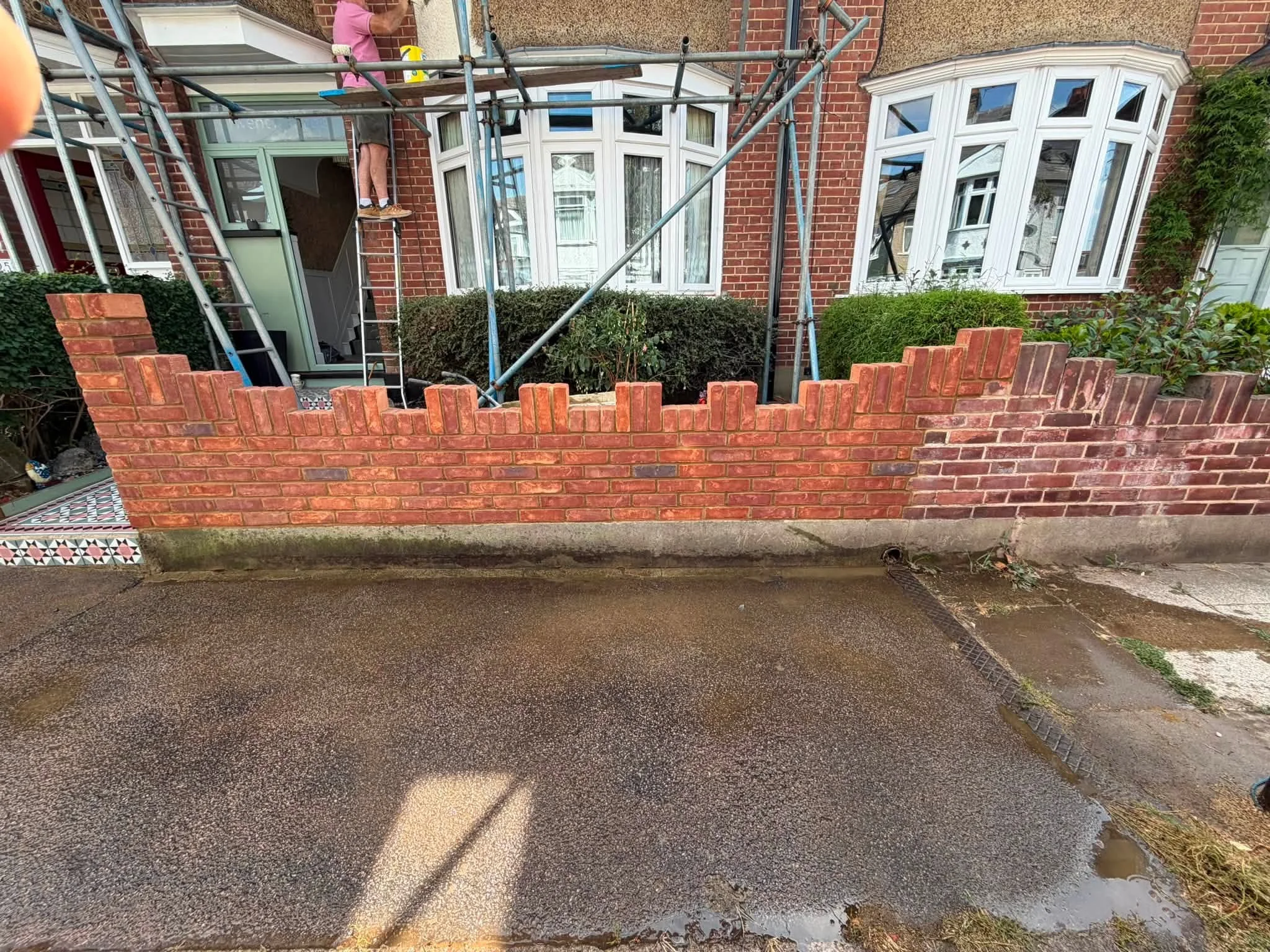
Master the civil engineering codes for structural masonry lintels, concrete padstones, and portal connections. Coordinate high-load brickwork kent facades with landscaping kent base interfaces.
Structural Masonry Lintels and Portal Connections: Engineering Clear-Span Load Redistribution Across Structural Brickwork Kent and Precision Landscaping Kent Interfaces
Creating wide architectural openings—such as expansive bi-fold doors, structural garage spans, or open-plan garden room transitions—requires an advanced understanding of structural mechanics, deflection limits, and load path redistribution. When a load-bearing wall is opened up to accept a wide glazed frame or clear-span gateway, the continuous vertical masonry support is interrupted. The dead loads from upper brick leaves, floor joists, and roof structures must be safely caught and transferred horizontally into adjacent masonry piers.
Across high-end residential extensions, commercial developments, and structural estate transformations, treating a structural lintel or steel portal frame as a basic drop-in beam is a major structural error. Installing under-spec lintels, omitting engineered padstones, or failing to anchor supporting piers against lateral movement leads to rapid structural defects. These include masonry sagging, ceiling plaster shear fractures, window frame binding, and localized masonry crushing.
This technical manual details the deflection mathematics, concrete padstone designs, temporary needle shoring methods, and site workflows required to deliver high-performance clear-span assets under a premier, fully integrated brickwork kent and landscaping kent delivery framework.
1. Structural Mechanics: Bending Moments, Deflection Limits, and Load Paths
Inserting a clear-span lintel or steel Universal Beam (UB) into a load-bearing wall transforms a continuous vertical compression path into a complex horizontal bending moment system.
Bending Strain and Eurocode Deflection Controls
The structural member must be sized under BS EN 1993 (Eurocode 3: Design of steel structures) and BS EN 1996 (Eurocode 6: Design of masonry structures) to handle both maximum bending moments and vertical shear forces. The maximum downward bending moment ($M_{max}$) for a uniformly distributed vertical load ($w$) across a clear span length ($L$) is calculated using the baseline structural equation:
$$M_{max} = \frac{w \cdot L^2}{8}$$
+-----------------------------------------------------------------------+
|                    CLEAR-SPAN LOAD REDISTRIBUTION CASCADE             |
+-----------------------------------------------------------------------+
|                                                                       |
|             [ OVERHEAD MASONRY LEAF & ROOF DEAD WEIGHTS ]             |
|                                   ||                                  |
|                                   v                                   |
|   +---------------------------------------------------------------+   |
|   | STEEL UNIVERSAL BEAM (UB) / COMPOSITE STRUCTURAL LINTEL       |   |
|   +---------------------------------------------------------------+   |
|          //                                               \\          |
|         // Concentrated Point Loads                        \\         |
|        v                                                     v        |
|   +-----------------------+                       +-----------------------+
|   | PRE-CAST C35 PADSTONE |                       | PRE-CAST C35 PADSTONE |
|   +-----------------------+                       +-----------------------+
|              ||                                              ||       |
|              v Stress Dispersed at 45°                       v        |
|   +-----------------------+                       +-----------------------+
|   | SUPPORTING BRICK PIER |                       | SUPPORTING BRICK PIER |
|   +-----------------------+                       +-----------------------+
|                                                                       |
+-----------------------------------------------------------------------+
To prevent cosmetic ceiling cracking and window binding, the member must meet strict Serviceability Limit State (SLS) deflection criteria. Total vertical deflection under full dead and live loads must not exceed $L/360$, or a maximum absolute limit of 10mm. If the beam flexes beyond this limit, the overhead brickwork will experience tensile cracking along the mortar joints above the center of the span.
2. Padstone Engineering: Concentrated Point Load Dispersion Profiles
Where a heavy steel beam or concrete lintel rests on a brickwork pier, it applies a massive, highly concentrated vertical point load. Because standard facing bricks have limited resistance to pinpoint crushing forces, this load must be diffused using an engineered pre-cast concrete padstone.
Dispersing Stress Across Supporting Masonry
A padstone acts as a dense structural cushion, spreading the concentrated downward force outward at a forty-five-degree angle. This increases the bearing area and reduces compressive stress until it falls safely within the characteristic strength capacity of the underlying brickwork.
+-----------------------------------------------------------------------+
|                    THE COMPRESSION STRESS PADSTONE CONE               |
+-----------------------------------------------------------------------+
|                                                                       |
|                      [ STEEL UNIVERSAL BEAM END ]                     |
|                                   ||                                  |
|                                   v Concentrated Point Load           |
|               +---------------------------------------+               |
|               | PRE-CAST C35/45 DENSE CONCRETE BLOCK  |               |
|               +---------------------------------------+               |
|                          /                 \                          |
|                         /                   \ 45° Stress Dispersion   |
|             +-------------------------------------------+             |
|             | SUPPORTING BRICKWORK PIER COMPRESSION BED |             |
|             +-------------------------------------------+             |
|                                                                       |
+-----------------------------------------------------------------------+
Padstones must be manufactured from high-density pre-cast concrete specified to a minimum compressive strength class of C35/45. The block is bedded onto the brick pier using a high-strength, non-shrink epoxy or polymer-modified mortar, eliminating air voids across the interface. Standard mortar or slate packings must never be used under high-load beam bearings, as they can crush under high compression, leading to pier failure.
3. Temporary Structural Support: Needle Shoring and Propping Mechanics
Before cutting out an existing wall or opening up a masonry leaf to install a new lintel, the overhead weight of the building must be completely bypassed using temporary needle shoring systems.
Isolating Active Load Paths During Demolition
The temporary support layout must be engineered to hold the full weight of the overhead structure while the masonry below is removed:
- Needle Beam Insertion: Heavy steel needle beams are passed through temporary holes drilled through the brick leaf directly above the planned cut line.
- Calibrated Prop Assembly: The ends of the needle beams are supported by adjustable steel props, which are torqued up until they actively accept the overhead structural load.
- Base Load Spreading: The base of every prop rests on thick timber sole boards distributed over compacted aggregate layers to prevent localized subgrade sinkage.
+-----------------------------------------------------------------------+
|                    ACTIVE NEEDLE SHORING LAYOUT                       |
+-----------------------------------------------------------------------+
|                                                                       |
|                  [ OVERHEAD BRICKWORK LEAF TO BE RETAINED ]           |
|                                      ||                               |
|   <=== STEEL NEEDLE BEAM ===> [ MASONRY POCKET ] <=== NEEDLE BEAM ===>|
|            ||                                             ||          |
|            v                                              v           |
|   +------------------+                           +------------------+ |
|   | STEEL ACROW PROP |                           | STEEL ACROW PROP | |
|   +------------------+                           +------------------+ |
|            ||                                             ||          |
|            v                                              v           |
|   =================================================================   |
|   [ TIMBER SOLE BOARDS & COMPACTED LANDSCAPING AGGREGATE BASE ]       |
|                                                                       |
+-----------------------------------------------------------------------+
This temporary propping system holds the building weight completely rigid throughout the demolition and beam setting phases, ensuring zero movement across the upper brickwork kent facade.
4. Sub-Surface Hydrology: Slot Drainage Networks and SuDS Integration
Managing rainwater runoff along the base of a clear-span opening—especially where wide glazed doors open onto flat patio surfaces—is critical to prevent water ingress and ground saturation.
Where a structural opening meets pedestrian courtyards, driveways, or garden terraces, the paving must be graded to fall away from the opening at a minimum slope gradient of 1 in 80. To catch sheet water runoff before it pools against the door threshold or brick piers, the perimeter must feature marine-grade stainless steel linear slot drainage channels.
+-----------------------------------------------------------------------+
|                    THE SUDS HYDROSTATIC ARCHITECTURAL ISOLATION LOOP  |
+-----------------------------------------------------------------------+
|                                                                       |
|     [ THRESHOLD & PAVING RUNOFF ] ===> [ GRADIENT FALL SURFACE ]      |
|                                                     ||                |
|                                                     v                 |
|                                       +--------------------------+    |
|                                       | LINEAR SLOT CHANNELS     |    |
|                                       +--------------------------+    |
|                                                     ||                |
|                                                     v                 |
|                                       +--------------------------+    |
|                                       | ATTENUATION SOAKAWAYS    |    |
|                                       +--------------------------+    |
|                                                     ||                |
|                                                     v                 |
|                                 [ CONTROLLED NATURAL INFILTRATION ]   |
|                                                                       |
+-----------------------------------------------------------------------+
These slot tracks feed directly into subterranean stormwater attenuation crate systems wrapped inside needle-punched geotextile filtration fabrics to satisfy Sustainable Drainage Systems (SuDS) mandates. This setup holds peak storm volumes underground, letting the fluid filter slowly back into the natural water table at a controlled rate, protecting surrounding landscaping kent hardscapes from standing water damage.
5. Material Performance Profiles: Structural Classifications
Selecting the correct materials requires matching core manufacturing and chemical metrics against the structural design constraints of your engineering plan:
[ MATERIAL MATRIX: Structural Steel Universal Beams (Grade S355) ]
- Minimum Yield Strength ($f_y$): 355 N/mm²
- Design Standard Compliance: BS EN 10025-2 (Hot rolled products of structural steels)
- Target Application: Wide clear-span lintels, heavy load-bearing opening supports, portal frame beams
[ MATERIAL MATRIX: Pre-Cast Concrete Padstones (Class C35/45) ]
- Compressive Strength: Greater than 45 N/mm² (28-Day Cube Strength)
- Manufacturing Density: 2,400 kg/m³ (Heavy-Duty Pre-Cast)
- Target Application: Beam bearing seats, point load dispersion blocks, pier caps
[ MATERIAL MATRIX: High-Strength Non-Shrink Epoxy Grout ]
- Compressive Strength Target: Greater than 70 N/mm²
- Volumetric Shrinkage Metric: Zero-Shrinkage Compound
- Target Application: Padstone bedding layers, beam head gap packing, dry-pack joint locks
6. Comprehensive Operational Phased Lifecycle for Structural Lintel and Portal Installations
To guarantee that every deflection calculation, temporary propping setup, padstone setting, and drainage tie-in complies with civil engineering codes, site management must enforce a strict, phased construction framework.
Phase 1: Site Profiling, GPR Utility Scanning, and Structural Calculations
Before any cutting or structural demolition begins on site, the ground parameters and structural prints must be fully verified.
- Deflection and Bending Calculations: Complete detailed structural calculations under Eurocode 3 and Eurocode 6 to confirm beam sizing and padstone dimensions.
- Subsurface GPR Utility Scanning: Scan the excavation perimeter using high-sensitivity Ground Penetrating Radar (GPR) to map all buried utility lines, power tracks, and drainage networks, establishing clear mechanical exclusion zones.
- Geotechnical Soil Profiling: Audit soil profiles beneath the supporting piers to confirm California Bearing Ratio (CBR) readings and verify subgrade clay stability.
Phase 2: Temporary Needle Shoring, Demolition, and Base Preparation
This phase manages the active isolation of overhead building weights and the physical cutting out of the masonry opening.
- Active Needle Shoring Assembly: Drill access pockets through the brickwork leaf, insert heavy steel needle beams, and torque up adjustable props over timber sole boards to take the building weight.
- Precision Masonry Demolition: Cut out the planned opening dimensions using low-vibration diamond saws, clearing away isolated brickwork while monitoring deflection gauges.
- Pier Bed Preparation: Rake out and level the masonry courses at the beam bearing points, preparing the pier faces to receive the concrete padstones.
Phase 3: Padstone Setting, Steel Erection, and Dry-Pack Joint Locking
The core construction phase where padstones are bedded, structural steel is raised, and joint loads are locked.
- Padstone Bedding: Bed the pre-cast C35/45 concrete padstones onto the supporting brick piers using non-shrink epoxy grout, ensuring absolute level alignment across the span.
- Steel Beam Erection: Raise the structural steel Universal Beam onto the padstones using mechanical hoists, aligning the bearing ends on elastomeric seating pads.
- Dry-Pack Head Joint Locking: Pack the gap between the top flange of the steel beam and the overhead brickwork with zero-shrinkage dry-pack mortar, allowing it to cure for 48 hours before striking the temporary propping system.
Phase 4: Slot Drain Integration, Hardscape Finishing, and Handover
The final technical phase where drainage tracks are connected, threshold paving is installed, and the site is certified for handover.
- Linear Slot Channel Matching: Position stainless steel linear slot drainage channels along the threshold base, linking the tracks directly to subterranean SuDS attenuation crate systems.
- Threshold Hardscape Assembly: Lay surrounding porcelain or natural stone paving fields, maintaining a 1 in 80 drainage fall away from the open doorway.
- Final Cleandown and Handover Sign-Off: Clean all facing brickwork elevations, inspect all beam bearing points and movement joints, and formally sign off the asset for immediate client handover.