Master the engineering of flush-threshold transformations in Kent. Learn to seamlessly coordinate structural brickwork, subgrade landscaping, and porcelain slabbing.
The execution of a seamless, flush-threshold transition—where internal home living spaces level out perfectly with external pedestrian terraces—is one of the most coveted configurations in modern luxury residential architecture. Achieving this continuous floor plane requires an absolute architectural handshake between three distinct engineering disciplines: structural masonry, civil earthworks, and precision hardscape installation.
Across properties in the South East, building a zero-step entrance over volatile ground profiles is a high-risk structural maneuver. If the threshold is executed without specialized linear sub-surface drainage tracks, step-down cavity tray membranes, and chemically decoupled sub-bases, the installation will fail. Rainwater will bridge the damp proof course, tracking inside to cause dry rot, while shifting subgrade clays will distort the external paving plates.
This comprehensive technical manual details the waterproofing mechanics, civil grade stabilization, and material connections required to deliver unyielding turnkey residential hardscaping kent assets.
1. Structural Masonry Modifications and Cavity Tray Waterproofing
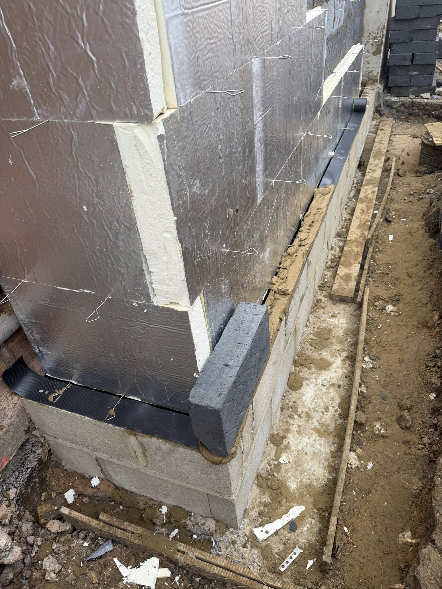
A standard external wall terminates its damp proof course (DPC) at least one hundred and fifty millimeters above the external ground level to prevent rainwater from bouncing upward and saturating porous brickwork. Sinking the external paving field to sit perfectly flush with the interior floor frame eliminates this safety margin, requiring advanced structural masonry re-engineering.
The Mechanics of Step-Down Cavity Trays
To maintain an absolute moisture barrier below the internal floor frame, the structural cavity wall assembly must incorporate a continuous, heavy-duty polyethylene step-down cavity tray membrane. The tray is bedded into the inner blockwork leaf directly beneath the structural floor joists and slopes downward across the one-hundred-millimeter insulation void, exiting through a lower horizontal mortar joint in the external brick leaf.
+-----------------------------------------------------------------------+
|                    THE STEP-DOWN CAVITY TRAY WATERPROOF BARRIER       |
+-----------------------------------------------------------------------+
|                                                                       |
|   [ INTERNAL FLOOR SUBSTRATE ]               [ EXTERNAL BRICK ]       |
|   ============================               +----------------+       |
|                ||                            |                |       |
|   (INNER DPC)  ||==\                         |                |       |
|   =============|    \  STEP-DOWN CAVITY TRAY |                |       |
|                ||    \======================>|==============  |       |
|                ||    (Continuous Fall Slope) |  WEEP VENT PORT|       |
|   +------------++                            +----------------+       |
|   | BLOCK LEAF |                             [ FLUSH PAVING ]         |
|                                                                       |
+-----------------------------------------------------------------------+
This structural slope ensures that any driving rain penetrating the external facing bricks hits the impervious tray and is directed safely outward rather than tracking horizontally to compromise the internal floor timber arrays.
To allow this collected moisture to exit the building envelope, the masonry courses directly above the paving line must feature vertical weep holes. These vents are formed by leaving vertical perpendicular joints entirely open at twelve-hundred-millimeter intervals, fitted with louvered plastic weep vents. Every adjacent masonry element must conform exactly to premium structural brickwork kent guidelines to prevent structural masonry failure paths.
2. Topographical Landscaping: Subgrade Stabilization Across Volatile Clays
Altering the landscape grade to match a flush internal threshold requires extensive, multi-level earthmoving operations. The civil groundwork crews must excavate deep beneath the door frame to clear away all soft, organic topsoils, establishing an unyielding foundation cushion capable of supporting the combined weights of the bedding mortars and stone slabs.
Neutralizing Volatile Wealden and London Clay Horizons
Paving teams across the South East continuously interface with highly challenging ground formations, notably the heavy, over-consolidated Wealden and London Clay shelves. Clay profiles exhibit high plasticity metrics and act like a geological sponge, expanding aggressively during wet winter saturation cycles and shrinking into deep cracks during dry summer spells.
To insulate the finished paving from these intense ground movements, the raw earth bed is lined with a heavy-duty, needle-punched non-woven geotextile segregation membrane. This fabric sheet acts as an absolute physical barrier that blocks the soft underlying clay from tracking upward into the clean aggregate foundation layers while permitting the free downward migration of groundwater.
Directly over this barrier, a minimum of one hundred and fifty millimeters of tightly graded Type 1 Granular Sub-Base stone is deposited and compacted using heavy mechanical vibrating plates until maximum dry density is achieved, matching the deep structural integrity targets enforced across premium landscaping kent frameworks.
3. Hardscape Slabbing Engineering: SBR Slurry Bonding and Joint Integrity
Once the granular sub-base platform is compacted and locked, the hardscape team constructs the rigid bedding layer to prepare for tile placement. For premium flush-threshold extensions, modern architectural designs specify large-format vitrified porcelain tiles or premium diamond-sawn natural stone flagstones.
Chemically Decoupling the Vitrified Base
Vitrified porcelain possesses an ultra-low water absorption profile of less than zero point five percent, meaning the tiles cannot absorb water or form a natural bond with a standard sand and cement mix. If a tile is laid straight onto a standard base, it will cleanly delaminate under temperature shifts.
+-----------------------------------------------------------------------+
|                    THE RIGID FULL-CONTACT BEDDING LAYER INTERFACE     |
+-----------------------------------------------------------------------+
|                                                                       |
|   [ VITRIFIED PORCELAIN / SAWN STONE PLATFORM ]                       |
|   =================================================================   |
|   [ POLYMER-MODIFIED SBR SLURRY PRIMER COATING FILL: 2mm SHIELD ]     |
|   =================================================================   |
|   [ CALIBRATED FOUR-TO-ONE SHARP SAND STRUCTURAL MORTAR BASE ]        |
|   +---------------------------------------------------------------+   |
|                                                                       |
+-----------------------------------------------------------------------+
To form an unbreakable adhesion bond, every porcelain unit must have a specialized polymer-modified Styrene-Butadiene Rubber (SBR) slurry primer coat applied across its entire rear face immediately before being set down onto a full-contact, four-to-one sharp sand and cement mortar bed.
The tile must be tapped down to flat coordinates using mechanical leveling clips, ensuring a continuous joint profile of three to five millimeters. The joints are then packed tight with high-density polymer grouts, sealing the platform against water ingress and protecting the global slabbing kent platform from structural damage.
4. Civil Hydraulic Routing and Sustainable Drainage (SuDS) Controls
Because a flush-threshold design eliminates the natural vertical step drop, it introduces a critical hazard: during heavy storm events, rain sheets hitting the patio surface can quickly pool against the door tracks, bypassing internal weather seals and flooding the home. To eliminate this risk, the terrace must incorporate an active sub-surface drainage network.
The Linear Slot Threshold Interception Matrix
The critical engineering asset utilized to protect the threshold is a high-capacity stainless steel linear slot drainage channel running directly parallel to the glazing tracks. As demonstrated in the fundamental floor-to-foundation connection principles mapped above, the external paving field must be laid with a continuous, precise drainage fall gradient to manage multi-wythe water loads.
The platform must tilt away from the house frame at a minimum slope profile of one in eighty—equal to twelve point five millimeters of vertical fall for every one meter of horizontal length. Rainwater sheets are captured by the slot channel, drop rapidly through the sub-surface matrix, and collect within a main catchment basin where they route into subterranean stormwater attenuation crate arrays wrapped in permeable geotextile filtration fabrics. This setup satisfies modern Sustainable Drainage Systems (SuDS) mandates, permanently protecting the building foundations from hydrostatic water pressure buildup.
5. Work Site Staging and Surface Protection Standards
The definitive marker of a premium turnkey contractor is how meticulously the masonry and hardscape technicians protect existing architectural profiles and finished external surfaces throughout the construction loop.
Masking Facades from Cement Etch Failures
Executing flush thresholds requires processing heavy cement aggregates, cutting masonry cavities, and pumping structural grouts, which generates massive volumes of highly alkaline silica dust and wet mortar splatters. If these cement residues drop onto unsealed sawn sandstone or premium porcelain pavers, the free-lime chemical compounds will etch into the stone pores, causing permanent staining that requires heavy industrial brick repair kent remediation to correct.
Construction Sub-SectorPrimary Waste Material RiskSurface Protection ProtocolFinal Structural BenefitStructural MasonryHigh-Alkaline Lime SlurriesThick Polythene WrappingEliminates brick face scalingCivil EarthworksAbrasive Clay & Stone ChipsGeotextile Shock MatsPrevents subgrade scratchingPrecision HardscapingExcess Polymer-Resin ResinsMulti-Layer Copolymer SheetingPreserves pristine tile finish
To preserve the assets, the entire workspace boundary beneath active scaffolding lifts must be fully wrapped in protective polythene sheeting and thick geotextile buffer mats. All wash water used to control dust must be collected by wet-vacuum extraction systems before it can enter external drainage tracks or pool across nearby high-load driveways. This maintains absolute environmental control and ensures the site is handed over to the client manager in flawless structural and visual condition.
6. Comprehensive Operational Phased Lifecycle for Turnkey Hardscape Synthesis
To guarantee that every structural cavity tray, subgrade compaction lift, SBR slurry bond, and SuDS slot drain interfaces flawlessly throughout the build loop, site management teams must enforce a strict, phased construction framework.
Phase 1: Topographical Mapping, GPR Scanning, and Design Plan Checks
Before any tools arrive on site, the structural ground parameters and layout dimensions must be fully checked and verified.
- Topographical Laser Surveys: Execute an exhaustive multi-axis laser scan across the threshold path to calculate the exact excavation depths and gradient lines required for the flush step transitions.
- Subsurface GPR Utility Scanning: Survey the entire construction footprint using high-sensitivity Ground Penetrating Radar (GPR) to map all buried main utility pipelines, power lines, and data conduits, establishing clear mechanical exclusion zones.
- Plan Check Approvals: Secure formal Building Control plan check sign-offs for all structural cavity tray extensions, padstone configurations, and global SuDS storm attenuation designs.
Phase 2: Volumetric Excavations, Geotextile Placement, and Sub-Base Compaction
This phase manages the physical cutting away of the terrain and constructs the unyielding structural foundation platforms.
- Volumetric Earth Excavations: Deploy compact tracked excavators to cut out the design grades, clearing away soft topsoils to expose stable subgrade clay strata, and route all waste soil away via certified muck-away transport loops.
- Geotextile Membrane Layout: Lay out the non-woven geotextile segregation sheets across the leveled earth beds, overlapping all seams by a minimum of three hundred millimeters to isolate the earth.
- Granular Aggregate Compaction: Deposit the clean MOT Type 1 aggregate in controlled seventy-five-millimeter layers, using heavy mechanical vibrating plate compactors to compact the stone matrix into an unyielding reservoir platform.
Phase 3: Cavity Tray Installations, SBR Slurry Coatings, and Tile Setting
The core construction phase where the waterproofing membranes are integrated and the rigid bedding stone field is executed.
- Structural Cavity Tray Mounting: Install the heavy-duty polyethylene step-down cavity tray membrane into the horizontal masonry courses, setting the louvered plastic weep vents at twelve-hundred-millimeter intervals.
- Mortar Mix Balancing: Mix the semi-wet four-to-one sharp sand and cement structural bedding mortar, distributing the paste evenly over the stone base to a uniform thickness of forty millimeters.
- Executing the SBR Rear Prime: Blend pure liquid SBR latex with neat Portland cement to a thick consistency, coating the entire rear face of every porcelain or natural stone tile with an absolute two-millimeter film shield immediately prior to laying.
Phase 4: Slot Drain Integration, Grouting, and Handover Surface Protection
The final technical phase where drainage systems are connected, joints are permanently sealed, and protection sheets are removed for final handover.
- Linear Slot Channel Matching: Position the stainless steel linear slot drainage channels parallel to the door frame tracks, connecting the lines directly to subterranean SuDS attenuation crate cells.
- Joint Grouting Execution: Pack the open joint channels completely with high-density polymer grouts, forcing the compound deep into the gaps using rubber jointing irons to eliminate internal air voids.
- Surface Cleansing and Handover Protection: Clean away all installation residues from the finished stone platforms, remove all surrounding wall perimeters and masking sheet layers, and formally sign off the turnkey hardscape asset for immediate handover.