Master the civil engineering codes matching structural brickwork kent facades with advanced landscaping kent extension foundations across volatile clay terrains.
The execution of a luxury residential home extension requires a seamless structural link between deep subterranean earth stabilization and flawless above-ground load-bearing masonry. Constructing a heavy, multi-story extension footprint involves shifting localized weight distributions. When new structural elements are anchored to an existing building envelope, the new foundation base must be engineered to settle uniformly with the heritage structure, eliminating any risk of differential movement along the connection joint.
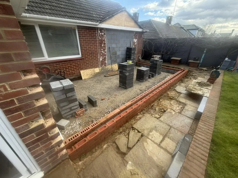
Across regional settings, failing to carefully coordinate the initial earth-moving phase with the subsequent structural masonry stages is a common point of failure. Erecting an extension envelope without assessing the shear strength of the subgrade, insulating foundation paths against winter frost heave, or installing heavy-duty cavity wall waterproofing layers leaves the building vulnerable to serious defects. These include structural masonry cracks, moisture bridging, and foundation shifting, which can compromise the safety and value of the entire property.
This comprehensive engineering manual details the soil mechanics, excavation rules, multi-wythe cavity wall codes, and site workflows required to build unyielding extension structures under a premier, fully integrated landscaping kent and brickwork kent delivery model.
1. Geotechnical Groundworks: Excavation Depth and Managing Foundation Settlement
Before any structural brick layers are laid, the sub-surface ground layers must be engineered to support the building's permanent vertical dead weight. The primary civil challenge is ensuring that the new foundation system does not cause rotational movement or stress fractures along the connection face of the existing property.
Managing Cohesive Clay Volatilities
Groundwork teams frequently encounter highly challenging, high-plasticity clay profiles, specifically the regional Wealden and London Clay tables. These clay formations are highly sensitive to hydrological shifts; they expand aggressively during wet winter saturation cycles and shrink into deep cracks during hot summer dry spells.
+-----------------------------------------------------------------------+
|                    THE EXTENSION COLLISION INTERFACE LAYER            |
+-----------------------------------------------------------------------+
|                                                                       |
|   [ EXISTING RESIDENCE FOOTING ]             [ NEW EXTENSION CORE ]   |
|   ==============================             ======================   |
|                 ||                                     ||             |
|   (Legacy Base) ||<========= DEEP CLAY MOVEMENT ======>|| (New Base)  |
|   ==============|   - Insulated with Clayboards        |============= |
|                 ||   - Bypasses upper moisture layers  |              |
|   +------------++                                      ++------------+|
|                                                                       |
+-----------------------------------------------------------------------+
To stabilize the extension permanently, civil earthmoving crews execute bulk excavations down to a minimum stable depth threshold of 1.0 to 1.5 meters, completely bypassing the unstable upper moisture-fluctuation layers.
The vertical sides of the foundation trench are lined with compressible low-density polystyrene clayboard sheets. These specialized buffers collapse safely under pressure, absorbing horizontal lateral soil expansion forces during wet weather cycles and protecting the newly poured concrete footings from intense ground heave.
2. Structural Foundation Design: Mass Concrete Strip Footings and Rebar Mesh
For traditional multi-wythe cavity walls, the primary substructure is a high-density, steel-reinforced mass concrete strip footing designed to distribute vertical compression forces uniformly into the underlying ground bed.
The Physics of Concrete Compression and Tensile Reinforcement
Concrete possesses exceptional compressive strength but limited tensile capacity when unreinforced. Because an extension applies eccentric vertical weights along its corners and roof lines, the concrete base experiences internal bending strains. To handle these multi-axial forces, the foundation must incorporate a high-tensile steel reinforcement bar mesh grid.
+-----------------------------------------------------------------------+
|                    THE REINFORCED MASONRY BEARING PLATFORM            |
+-----------------------------------------------------------------------+
|                                                                       |
|             [ HEAVY MULTI-WYTHE STRUCTURAL CAVITY WALL RUN ]          |
|                                   ||                                  |
|                                   v                                   |
|         +------------------------------------------------------+      |
|         | HIGH-DENSITY C25/30 STRUCTURAL CONCRETE FOOTING REFT  |     |
|         +------------------------------------------------------+      |
|         | [O] [O]  VERTICAL STEEL STARTER REBAR BARS     [O] [O] |    |
|         |======================================================|      |
|         | HIGH-TENSILE A393 APEX STRUCTURAL STEEL REBAR MESH   |      |
|         +------------------------------------------------------+      |
|                                   ||                                  |
|                                   v Distributes Total Weight Safely   |
|   =================================================================   |
|   [ UNYIELDING STABLE SUBGRADE STRATA CORES ]                         |
|                                                                       |
+-----------------------------------------------------------------------+
The steel rebar cages are elevated on concrete spacer blocks to guarantee a minimum fifty-millimeter concrete cover coat, shielding the steel core from groundwater corrosion.
Structural concrete, specified to a minimum class designation of C25/30 or Generic Gen 3 concrete, is poured into the trench in continuous volume streams. The mix is processed using mechanical internal poker vibrators to extract all trapped air bubbles, creating a dense, void-free foundation platform capable of supporting the high-load masonry above.
3. Structural Masonry Configurations: Cavity Widths, Wall Ties, and Thermal Blocks
Once the subterranean concrete footings have achieved their full twenty-eight-day design strength, the masonry teams begin raising the extension envelope in accordance with BS EN 1996 (Design of masonry structures).
Optimizing the Cavity Shield Matrix
A high-performance extension envelope relies on a double-skin cavity wall layout. This configuration isolates the internal living space from external environmental factors through a clear structural void:
- The Outer Facing Skin: Built using frost-resistant, low-porosity engineering bricks or premium handmade facing blocks, matching the aesthetic character of the original building.
- The Insulation Cavity Void: A one-hundred-and-fifty-millimeter horizontal gap packed with high-density rigid polyisocyanurate (PIR) insulation boards, leaving a clear fifty-millimeter air space to prevent moisture tracking.
- The Inner Inner Leaf: Constructed using high-strength, lightweight aerated thermal blockwork to maximize interior thermal mass and limit heat loss.
+-----------------------------------------------------------------------+
|                    THE CAVITY STRUCTURAL MOISTURE BREAK               |
+-----------------------------------------------------------------------+
|                                                                       |
|   [ FACING SKIN ]          [ PIR INSULATION ]          [ INNER BLOCK ]|
|   +-------------+           ||||||||||||||||           +-------------+|
|   | Brickwork   |           |  100mm RIGID |           | Aerated     ||
|   | (Flemish)   |<=========>|  INSULATION  |<=========>| Structural  ||
|   | Outer Leaf  |  Wall Tie |  BOARD TRACK |  Wall Tie | Thermal Leaf||
|   +-------------+           ||||||||||||||||           +-------------+|
|                                                                       |
+-----------------------------------------------------------------------+
To tie the inner and outer leaves into a single structural unit, technicians install stainless steel retention ties spaced every four hundred millimeters vertically and nine hundred millimeters horizontally. These wall ties feature a central drip loop pointing downward into the cavity. This simple geometric design forces any tracking moisture drops to break contact and fall down to the base of the cavity, keeping the interior wall leaf bone dry.
4. Sub-Surface Hydrology: Waterproofing Cavity Trays and Sustainable Drainage
Sinking an extension foundation base next to existing building footprints creates a critical water management challenge: surface water tracking down the old brick faces can seep into the new internal living zones if it isn't properly intercepted.
To eliminate this damp risk, the intersection courses must feature a continuous, heavy-duty polymeric step-down cavity tray membrane. The tray is bedded into the horizontal mortar courses of the inner leaf, slopes downward across the insulation void, and exits through the outer brickwork face. Vertical perpendicular joints directly above the cavity tray are left open at regular intervals and fitted with louvered plastic weep vents, allowing any collected moisture to drain safely outward.
Furthermore, to manage heavy roof runoff from the new extension, the surrounding patio zones must feature high-capacity stainless steel linear slot drainage channels. These tracks route surface water directly into subterranean stormwater attenuation crate arrays wrapped in permeable geotextile filtration fabrics to satisfy Sustainable Drainage Systems (SuDS) mandates. This setup keeps the building base clear of standing water, permanently protecting the structural foundations from hydrostatic water pressure buildup.
5. Material Performance Profiles: Structural Classifications
Selecting the correct wood specification requires analyzing core timber metrics against the structural design constraints of the building plan:
[ MATERIAL COMPONENT: Class A Engineering Bricks ]
- Characteristic Compressive Strength: Greater than 125 N/mm²
- Maximum Water Absorption Capacity: Less than 4.5%
- Target Structural Zone: Below-ground foundation courses, damp-proof paths, high-load base layers
[ MATERIAL COMPONENT: Thermal Insulation Blocks ]
- Characteristic Compressive Strength: 3.6 N/mm² to 7.3 N/mm²
- Thermal Conductivity Value: 0.11 W/mK
- Target Structural Zone: Internal load-bearing leaves, inner extension wall insulation linings
[ MATERIAL COMPONENT: Structural Concrete Class C25/30 ]
- Characteristic Compressive Strength: 30 N/mm² (Cube Strength)
- Slump Fluid Consistency Metric: S3 Class (Flow Calibrated)
- Target Structural Zone: Mass concrete strip footings, reinforced foundation pad blocks
6. Comprehensive Operational Phased Lifecycle for Extension Construction
To guarantee that every sub-surface earthworks pass, concrete footing pour, cavity tie assembly, and architectural pointing line complies with building control standards, site management must enforce a strict, phased construction framework.
Phase 1: Site Multi-Axis Laser Profiling, GPR Scanning, and Footing Computations
Before any heavy mechanical civil equipment or plant cuts into the property boundary, the layout markings and underground parameters must be fully checked and verified.
- Laser Alignment Sweeps: Set up multi-axis line laser levels across the connection faces to map the exact leveling lines relative to the legacy property's damp-proof courses.
- Subsurface GPR Utility Scanning: Scan the entire excavation perimeter using high-sensitivity Ground Penetrating Radar (GPR) to map all buried utility lines, power tracks, and water mains, setting up strict mechanical exclusion zones.
- Geotechnical Soil Audits: Collect core soil samples across the extension zone to confirm California Bearing Ratio (CBR) readings and establish baseline clay plasticity index markers.
Phase 2: Volumetric Excavations, Shoring Assemblies, and Foundation Concrete Pours
This phase manages the physical cutting away of the terrain and constructs the deep concrete anchor foundation platforms.
- Volumetric Earth Excavations: Deploy tracked excavators to cut out the design trenches, clearing away soft topsoils down to stable subgrade clay strata, and route all waste soil away via certified muck-away transport loops.
- Shoring and Heave Board Layouts: Install high-strength steel trench sheets to protect the open paths, and line the vertical faces with low-density polystyrene clayboard sheets to absorb ground heave.
- Casting Mass Concrete Footings: Pump high-density C25/30 structural concrete into the trenches, processing the wet matrix with internal mechanical vibrators to extract all air voids.
Phase 3: Masonry Leaf Assemblies, Insulation Packaging, and Tie Integrations
The core construction phase where the extension walls are raised and structural joints are mechanically locked.
- Outer Facing Leaf Assemblies: Lay the selected frost-resistant facing bricks to strict horizontal level lines, maintaining a regular bonding pattern that matches the original home.
- Insulation Board Placement: Mount the rigid PIR insulation boards tightly against the inner face of the brickwork, keeping a clean fifty-millimeter air void clear of mortar drops.
- Inner Blockwork Erection: Build out the internal load-bearing leaf using high-strength thermal blocks, installing stainless steel cavity ties every four hundred millimeters vertically.
Phase 4: Cavity Tray Systems, Joint Tooling, and Handover Surface Cleandowns
The final technical phase where waterproofing membranes are connected, joints are tooled, and the completed structure is certified for handover.
- Waterproofing Cavity Tray Mounting: Install the heavy-duty polymeric step-down cavity trays across the junction courses, setting the vertical louvered weep vents at regular intervals.
- Joint Tooling Execution: Tool the open horizontal and vertical joints using compressed bucket-handle or weather-struck irons, forcing the compound deep into the gaps to eliminate internal air voids.
- Surface Cleansing and Handover Sign-Off: Clean away all installation residues from the completed brick elevations, remove all surrounding perimeters and masking sheet layers, and formally sign off the asset for immediate turnkey handover.