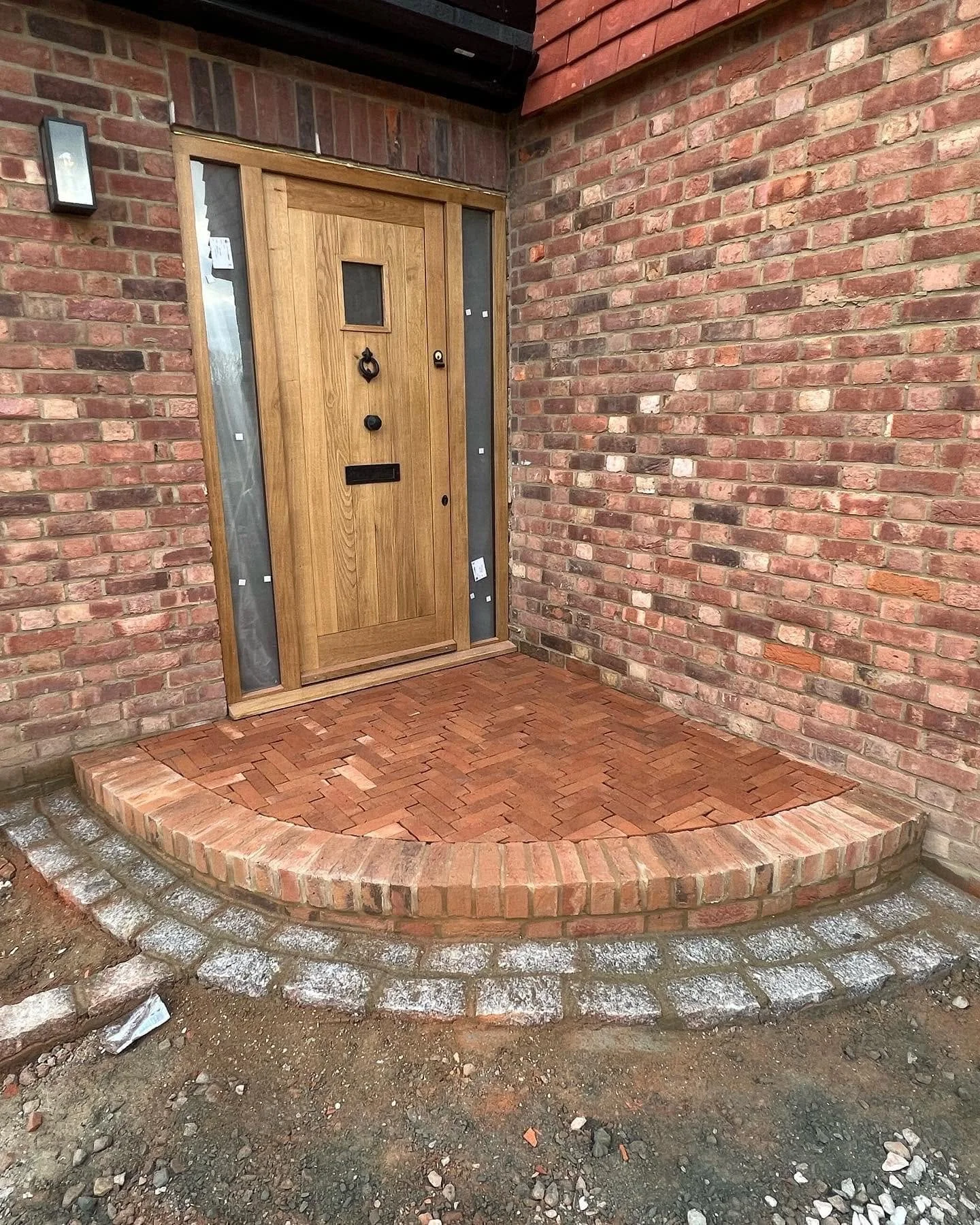
Master the civil engineering standards for multi-wythe load-bearing brickwork kent structures. Optimize cavity tie distributions and landscaping kent base interfaces.
Constructing high-load multi-wythe masonry elevations, structural boundary enclosures, and architectural garden walls requires a total integration of structural mechanics, thermodynamics, and sub-surface civil groundworks. A multi-wythe brick wall is a complex composite structure. It must continuously support vertical dead loads from upper roof structures, withstand dynamic horizontal wind-shear vectors, and isolate interior living or outdoor entertainment zones from water ingress.
Across high-end residential extensions, structural estate transformations, and commercial developments, treating a load-bearing brick wall as a basic decorative facade is a critical engineering error. Erecting multi-wythe brick runs without calculating eccentric load paths, balancing mortar strength profiles, or isolating base masonry courses from volatile subgrade clays leads to rapid structural defects. These include shear cracking, damp bridging, efflorescence staining, and localized structural failure under extreme weather events.
This technical manual details the structural mechanics, cavity tie distributions, moisture isolation details, and site workflows required to deliver high-performance masonry assets under a premier, fully integrated brickwork kent and landscaping kent delivery framework.
1. Structural Mechanics: Multi-Wythe Load Paths and Cavity Tie Dynamics
A multi-wythe cavity wall functions as a single cohesive structural unit where two independent leaves of masonry are tied together across an open air cavity. The outer facing leaf absorbs weather impacts, while the inner blockwork or brick leaf handles the primary vertical load paths.
Calculating Compressive Stress and Wall Tie Distributions
The total compressive load applied to the wall must be safely distributed across both leaves without exceeding the characteristic compressive strength ($f_k$) of the combined masonry and mortar assembly. Under BS EN 1996 (Design of masonry structures), mechanical wall ties link the two leaves together to share horizontal wind loads and prevent independent lateral buckling.
+-----------------------------------------------------------------------+
|                    MULTI-WYTHE CAVITY WALL FORCE DYNAMICS             |
+-----------------------------------------------------------------------+
|                                                                       |
|   [ EXTERNAL FACING LEAF ]     [ CAVITY VOID ]     [ INTERNAL LEAF ]  |
|   +----------------------+     |150mm VOID|     +------------------+  |
|   | Facing Brickwork     |     |          |     | Structural Block |  |
|   | (Flemish Bond)       |<===>| WALL TIE |<===>| Load-Bearing Leaf|  |
|   | Weather Barrier      |     | DRIP LOOP|     | Main Compression |  |
|   +----------------------+     |          |     +------------------+  |
|              ||                |          |              ||           |
|              v                 +----------+              v            |
|   =================================================================   |
|   [ DENSE HIGH-STRENGTH FOUNDATION FOOTING BLOCK PLATFORM ]           |
|                                                                       |
+-----------------------------------------------------------------------+
Technicians install stainless steel retention ties spaced at a maximum density of 4.4 ties per square meter (225mm vertical spacing by 900mm horizontal spacing). Around un-bonded edges, such as window openings, door frames, and vertical movement joints, the tie density increases to every 300mm vertically. Each wall tie features a downward drip loop positioned precisely in the center of the cavity. This geometry breaks water contact, forcing moisture tracking across the tie to drop down into the clear cavity void rather than crossing to the interior leaf.
2. Geotechnical Earthworks: Subgrade Soil Stabilization Across Regional Clays
The long-term alignment of a multi-wythe brick wall depends on the stability of the foundation subgrade beneath it. Civil groundwork teams frequently encounter challenging, high-plasticity clay profiles, specifically the regional Wealden and London Clay tables.
Clay formations expand aggressively during wet winter saturation cycles and shrink into deep cracks during hot summer dry spells. If a structural footing is cast within this unstable upper soil zone, the foundation will experience uneven vertical movement, causing structural shear cracks across the brickwork face.
+-----------------------------------------------------------------------+
|                    DEEP CONCRETE FOOTING CLAY STABILIZATION           |
+-----------------------------------------------------------------------+
|                                                                       |
|         [ MULTI-WYTHE STRUCTURAL LOAD-BEARING BRICKWORK WALL ]        |
|                             ||                                        |
|       === GROUND PROFILE ===||======================================  |
|                             v                                         |
|         +---------------------------------------+                     |
|         | REINFORCED CONCRETE STRIP FOOTING RAFT|                     |
|         | - Wrapped in Geotextile Layers        |                     |
|         | - Decoupled with Polystyrene Boards   |                     |
|         +---------------------------------------+                     |
|                             ||                                        |
|                             v Bypasses Volatile Soil Layers           |
|       - - - - - - - - - - - - - - - - - - - - - - -                   |
|        UNSTABLE UPPER SOIL PLASTIC MOVEMENT LAYERS                    |
|       - - - - - - - - - - - - - - - - - - - - - - -                   |
|                             ||                                        |
|                             v                                         |
|         [ STABLE DEEP-BEDDED GEOTECHNICAL CLAY STRATUM ]              |
|                                                                       |
+-----------------------------------------------------------------------+
To stabilize the infrastructure permanently, civil earthmoving crews execute trench excavations down to stable subgrade strata (minimum 1.2m depth). The vertical sides of the footing trench are lined with compressible low-density polystyrene boards, which absorb horizontal soil swelling forces during wet winter months. The raw trench base is lined with a needle-punched non-woven geotextile membrane before pouring C25/30 structural concrete, creating a firm base for both the brick structure and surrounding landscaping kent works.
3. Mortar Mechanics and Moisture Deflection: Calibrating Joints and DPC Shields
The selection of mortar mix composition governs the flexural strength and durability of the entire wall assembly. Mortar must cushion individual brick units, distribute compressive loads uniformly, and accommodate thermal expansion without cracking.
Mortar Designation Profiles and Application Zones
Mortars are specified under strict engineering classes based on their active cement, lime, and sand aggregate ratios:
[ MORTAR DESIGNATION: Class M12 / Class I ]
- Mix Proportion Ratio: 1 : 0.25 : 3 (Portland Cement : Lime : Sand Aggregates)
- Compressive Strength Target: 12.0 N/mm²
- Target Application: Below-ground foundation courses, damp-proof capping courses, retaining wall bases
[ MORTAR DESIGNATION: Class M6 / Class II ]
- Mix Proportion Ratio: 1 : 0.5 : 4.5 (Portland Cement : Lime : Sand Aggregates)
- Compressive Strength Target: 6.0 N/mm²
- Target Application: External facing brick elevations, high-exposure boundary structures
Integrating Damp-Proof Courses (DPC) and Weep Vents
To prevent groundwater from rising through the porous brickwork via capillary action, a continuous high-performance polymeric damp-proof course (DPC) is bedded across both the inner and outer leaves at a minimum height of 150mm above the final external ground level.
+-----------------------------------------------------------------------+
|                    THE DPC MOISTURE DEFLECTION INTERFACE              |
+-----------------------------------------------------------------------+
|                                                                       |
|   [ FACING BRICK SKIN ]                                               |
|   +-------------------+                                               |
|   | Open Weep Vent    |<=== Discharges Trapped Water Outward          |
|   +-------------------+                                               |
|   =================================================================   |
|   [ POLYMERIC DAMP-PROOF COURSE (DPC) LAYER - Minimum 150mm Above ]   |
|   =================================================================   |
|   | Subterranean Base |                                               |
|   +-------------------+                                               |
|                                                                       |
+-----------------------------------------------------------------------+
Directly above the DPC line, open vertical perpendicular joints (weep vents) are placed every third brick interval. Any moisture that enters the cavity void tracks down to the DPC sheet and flows outward through these weep vents, preventing dampness from bridging into internal spaces or degrading lower brickwork kent masonry courses.
4. Sub-Surface Hydrology: Slot Drainage Networks and SuDS Integration
Managing rainwater runoff along the base of an extended multi-wythe wall is essential for long-term structural health. Without active water management, standing water can saturate the ground, soften foundation soils, accelerate salt efflorescence staining, and cause freeze-thaw frost damage during winter freezes.
Where a structural wall meets pedestrian courtyards, driveways, or terraced garden borders, the ground must be graded to fall away from the brick face at a minimum slope gradient of 1 in 80. To capture surface water before it pools against the wall base, the perimeter must feature marine-grade stainless steel linear slot drainage channels.
+-----------------------------------------------------------------------+
|                    THE SUDS HYDROSTATIC ARCHITECTURAL ISOLATION LOOP  |
+-----------------------------------------------------------------------+
|                                                                       |
|     [ ROOF & PAVING RUNOFF ] ===> [ GRADIENT FALL SURFACE ]           |
|                                                     ||                |
|                                                     v                 |
|                                       +--------------------------+    |
|                                       | LINEAR SLOT CHANNELS     |    |
|                                       +--------------------------+    |
|                                                     ||                |
|                                                     v                 |
|                                       +--------------------------+    |
|                                       | ATTENUATION SOAKAWAYS    |    |
|                                       +--------------------------+    |
|                                                     ||                |
|                                                     v                 |
|                                 [ CONTROLLED NATURAL INFILTRATION ]   |
|                                                                       |
+-----------------------------------------------------------------------+
These slot tracks feed directly into subterranean stormwater attenuation crate systems wrapped inside needle-punched geotextile filtration fabrics to satisfy Sustainable Drainage Systems (SuDS) mandates. This setup holds peak storm volumes underground, letting the fluid filter slowly back into the natural water table at a controlled rate, protecting the wall foundations from hydrostatic water pressure buildup.
5. Material Performance Profiles: Structural Classifications
Selecting the correct materials requires matching core manufacturing and chemical metrics against the structural design constraints of your engineering plan:
[ MATERIAL MATRIX: Class A Engineering Bricks ]
- Compressive Strength: Greater than 125 N/mm²
- Water Absorption Capacity: Less than 4.5%
- Target Zone: Subterranean footing courses, damp-proof boundary lines, high-load base layers
[ MATERIAL MATRIX: Frost-Resistant Facing Bricks (F2 Rating) ]
- Compressive Strength: 30 N/mm² to 45 N/mm²
- Durability Rating: Freeze-Thaw Frost Resistant (F2), Low Soluble Salts (S2)
- Target Zone: Above-ground aesthetic wall panels, feature piers, decorative copings
[ MATERIAL MATRIX: Stainless Steel Cavity Wall Ties ]
- Material Grade Specification: Austenitic Stainless Steel (Grade 304 / 316)
- Design Standard Compliance: BS EN 845-1 (Specification for ancillary components for masonry)
- Target Zone: Cavity wall interlocks, movement joint tie systems
6. Comprehensive Operational Phased Lifecycle for Multi-Wythe Masonry Construction
To guarantee that every foundation pour, wall tie placement, cavity tray setting, and drainage tie-in complies with civil engineering codes, site management must enforce a strict, phased construction framework.
Phase 1: Site Profiling, GPR Utility Scanning, and Load Computations
Before any heavy tracked civil equipment or excavation plant enters the site, the ground conditions and layout parameters must be fully verified.
- Compressive Load Calculations: Complete detailed structural load calculations under BS EN 1996 to confirm required foundation widths and wall tie densities.
- Subsurface GPR Utility Scanning: Scan the entire construction footprint using high-sensitivity Ground Penetrating Radar (GPR) to map all buried utility lines, power tracks, and drainage networks, establishing clear mechanical exclusion zones.
- Geotechnical Soil Profiling: Audit raw soil profiles adjacent to the wall trench to confirm California Bearing Ratio (CBR) readings and establish baseline clay plasticity index markers.
Phase 2: Trench Excavations, Soil Shoring, and Mass Concrete Footing Pours
This phase manages the bulk physical earthworks and constructs the structural foundation platforms.
- Volumetric Trench Excavation: Deploy tracked excavators to dig out footing trenches down to stable subgrade strata, shoring vertical clay faces with temporary sheets to prevent bank collapse.
- Geotextile and Buffer Placement: Line the trench base with needle-punched non-woven geotextile segregation sheets and fit polystyrene heave boards along the vertical faces.
- Casting Concrete Footings: Position steel rebar cages and pour C25/30 structural concrete in continuous volume streams, using internal mechanical vibrators to eliminate air voids.
Phase 3: Leaf Assemblies, Cavity Insulation, and DPC Installations
The core construction phase where the multi-wythe leaves are raised and moisture barriers are installed.
- DPC and Weep Vent Mounting: Bed the continuous polymeric DPC membrane across both leaves at 150mm above finished ground level, installing open weep vents every third perpendicular joint.
- Multi-Wythe Superstructure Erection: Lay facing bricks and structural blockwork to strict horizontal level lines using M6 mortar, maintaining a regular Flemish or English bond pattern.
- Wall Tie Placement: Install stainless steel cavity wall ties at required densities (4.4 ties/m²), ensuring central drip loops point downward into the clear cavity void.
Phase 4: Slot Drain Integration, Terrace Hardscaping, and Handover
The final technical phase where drainage systems are connected, surrounding paving is completed, and the site is certified for handover.
- Linear Slot Channel Matching: Position the stainless steel linear slot drainage tracks parallel to the wall base, linking the channels directly to subterranean SuDS attenuation crate systems.
- Terrace Hardscape Assembly: Lay the surrounding paving fields or lawns, maintaining a 1 in 80 drainage fall away from the brick elevation.
- Final Cleandown and Handover Sign-Off: Clean all facing brickwork with non-acidic solutions, inspect all weep vents and movement joints, and formally sign off the asset for immediate client handover.